Last update on 22/05/2021
Continuous Mandatory Ventilation
Introduction
The idea of this project is to automize the speed regulation of Continuous Mandatory Ventilation (VMC) regarding a relative humidity.
The built module makes these things:
-
gets measurements from a humidity sensor,
-
receives commands from a simple HTTP server via wifi,
-
sends measurements to a database via wifi,
-
controls the VMC relays regarding a measured humidity.
Hardware
Modules

Power Supply
A component used to make a 3V3 stable voltage is AMS1117-3.3:

If it's necessary to power the module from battery, you should see the MCP1702-3302 with a low quiescent current:

A 3-pin connector is used to connect the input voltage with the board:

DHT22
To be completed.
ESP8266
To be completed.
7-Pin Connector
| Pin | Name | Wire Color |
|---|---|---|
| 1 | GND | Black |
| 2 | RX | White |
| 3 | Reserved* | - |
| 4 | TX | Yellow |
| 5 | Boot by GPIO0** | Green |
| 6 | N.C. | - |
| 7 | N.C. | - |
* Reserved: Compatibility another project
** Boot by GPIO0: N.C. – Flash boot, GND – UART boot
Boards Changelog
v2.0 - WIFI Connection & Debug Connector
Below you can find how looks like a pcb design of this version:
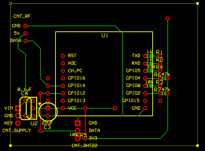
Changelog vs v1.0:
- Added a 7-pin connector.
This board version is used for CMV speed regulation. It is supplied directly from a 220V USB adapter to not bother about battery connection and charging. A consumption power is about 0.3W.
v1.1 - Low Consumption Temperature Sensor
Changelog vs v1.0:
-
Changed the supply component from AMS1117 to MCP1702.
-
Added a 7-pin connector.
-
Integrated 9V battery directly in the box.
-
Removed LED and 433 MHz transmitter.
This board version is used for an autonomous temperature / humidity measurements where a power consumption becomes critical.
v1.0 - Initial Version without WIFI Connection
Initial board version.
Extra Information
Some more information about hardware design can be found in this document (PDF).
Firmware
Configuration File
It is necessary to create a config.h file with this content:
#ifndef CONFIG_H
#define CONFIG_H

/* Wifi */
const char * CONFIG_WIFI_SSID = <your-wifi-ssid>;
const char * CONFIG_WIFI_PASSWORD = <your-wifi-password>;

/* DIO identification number of 26 bits, you can choose a random number */
const uint32_t CONFIG_DIO_ID = <int>;

/* deep sleep in sec after each humidity regulation */
const int32_t CONFIG_SLEEP_EACH_ITER_S = 30;

/* number of deep sleeps before connection to wifi to download / upload information */
const int32_t CONFIG_FORCE_UPDATE_ITER_NB = 60;

/* mysensors node id (see MySensors documentation for more information) */
const int32_t CONFIG_MYSENSORS_NODE_ID = <int>;

/* mysensors IP address */
const char * CONFIG_MYSENSORS_IP = "<int>.<int>.<int>.<int>";

#endif
Source Code
Source code of this project:
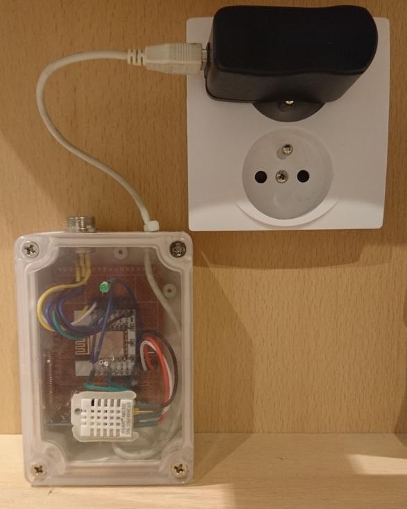
Conclusion
The board is working already for a while. Below you can find how the board looks like in the real life: